Fired Heater Rating and Simulation Software
Direct Fired Heaters are a critical component of many refining and petrochemical processes. They must be configured correctly to ensure efficiency and optimum plant performance.
WinHeat4.5, the latest version of the WinHeat suite of software, rates and simulates direct fired heaters, giving more control to the engineer or designer. It also rates convections, unfired and supplementary fired heat recovery units.
This program is designed to provide an engineer with the ability to evaluate direct fired process heaters of the type generally used in the petroleum and chemical industries. This evaluation may range from a simple thermal rating check to a complete design.
Features
For beginners and general users
Complete suite for all aspects of Fired Heater Rating and Simulation. Quick simulations with pre-fed defaults.
Quick Calculations
The software comes with pre-fed defaults so that a user can quickly start modeling the heater and evaluating the results.
Multiple tube sizes and materials in Radiant Section
Allows up to six tube sizes/materials or segments in radiant
Multiple segments in Convection Section
Allows up to ten tube sizes/materials or segments in convection
Multiple Processes
Allows up to six process streams in the convection section
Configurations with APH
Takes into account preheated combustion air and calculates system efficiency
Extensive Help
Help files that come with Winheat provide clear step by step usage instructions. Also, all formulae used in the calculations are provided
For advanced users
Ability to control the calculation factors and methods. Detailed output along with intermediate calculation results.
Extremely configurable and convenient
Advanced users can select inside rate calculation, set specific thermal rating factors for modeling to an exact fit
Detailed Output
The program output has details of calculations including intermediate calculation results. Program comes with details of all backup calculations and formulae used. A user may verify any portion of the output himself.
Model any heater
Most heater configurations are available ready. Configurations not exactly fitting these criteria may be rated by simply inputting actual dimensions and tube counts, etc.
Complex scenarios
Heaters having only convection or only radiant section can be simulated. Also, complex configurations, e.g. where multiple radiants feed to a common convection can be modeled by modeling each section separately.
External Flue Gas Sources
Allows introduction of an external flue gas source to convection section at any level
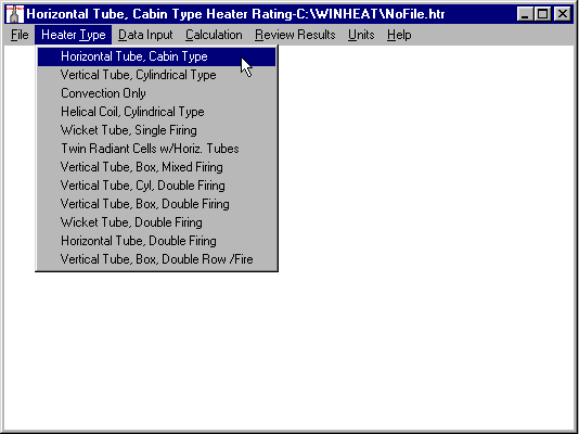
Heater Configurations
|
Description |
Firing |
|---|---|
|
Horizontal Tube, Cabin Type |
Single sided |
|
Vertical Tube, Cylindrical |
Single Sided |
|
Convection Section Only |
Supplementary/Auxiliary |
|
Helical Tube, Cylindrical |
Single Sided |
|
Vertical Wicket Tube |
Single Sided |
|
Horizontal Tube, Twin Box |
Single Sided |
|
Vertical Tube, Box |
Mixed |
|
Vertical Tube, Cylindrical |
Double Sided |
|
Vertical Tube, Box |
Double Sided |
|
Wicket Tube |
Double Sided |
|
Horizontal Tube |
Double Sided |
|
Vertical Tube, Box |
Double Sided |
|
CO Furnace/Boiler |
Auxiliary Combustor |
|
NOTE: Configurations not exactly fitting these criteria may be rated by simply inputting actual dimensions and tube counts, etc. |
|
Detailed Description
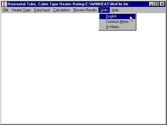
All data and inputs can be saved to computer data files for later use or modification. The detailed outputs give all input data provided as well as computed data. Unit selection is available in English, Common Metric and SI Metric.
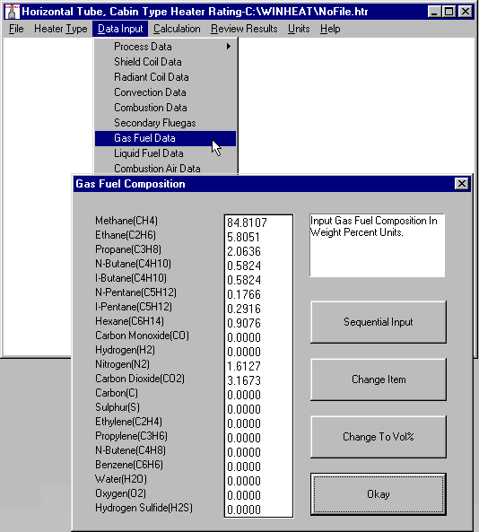
The program allows input of air and fuel gas compositions in either volume or weight percent. Liquid fuel compositions are input in weight percent. All required combustion properties, gas properties, enthalpies, etc., are computed by the program.
All thermal rating and heat transfer factors can be modified by the user, allowing an existing heater design to be precisely modeled, even with poor heat distribution, damaged extended surface, etc. Once an existing heater is modeled to existing operating conditions, a future operation may then be analyzed.
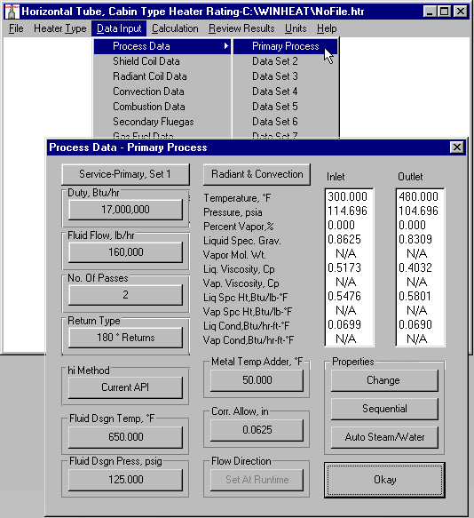
Process conditions and properties are input for the expected inlet and outlet points or from a grid file input by the user or generated by the program.
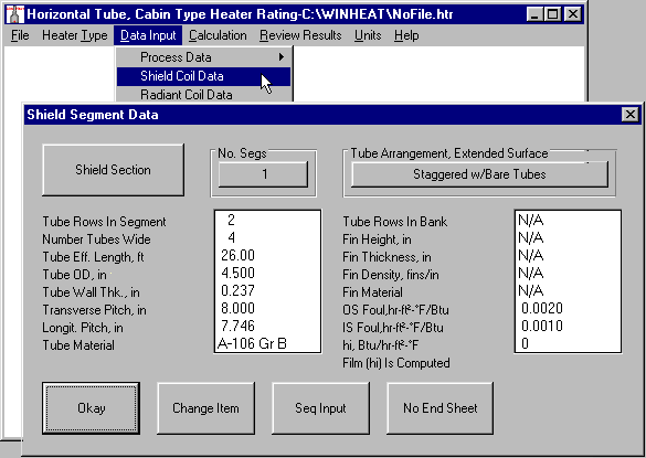
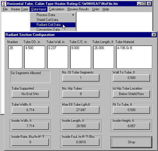
Coil section mechanical data is input by the user, except that metal thermal conductivity and inside heat transfer rates may be computed by program or input by the user. Many common specifications for the tubes and extended surfaces are available in the program selection. If desired metallurgy is not built-in, user may input description and conductivity value to be used. If the user elects to have the inside heat transfer rate computed, the method may be selected by the user from a selection of various methods. The heat transfer computations can be selected with the primary process flow in the convection section in either an upflow (co‐current) or downflow(counter‐current) configuration. Shield and radiant sections will be calculated in downflow configuration. Other data such as process side and gas side pressure drops are also computed by the programs. Heaters may be evaluated with or without a convection section and or shield section. Shield sections maybe two or three rows of tubes. A convection section can be evaluated individually.
Radiant heat absorption can be calculated for single rows of tubes against a refractory wall being fired from one side only or for a single row of tubes being fired from both sides and a combination of the two conditions. Many arrangements and configurations are supported by the program. These predefined arrangements and configurations allow the program to compute the heater dimensions. This feature also allows the thermal data file to be analyzed by the material take‐off and cost estimating program, avoiding the necessity of the user reentering data required by this program. However, many of the version two arrangements allow complete flexibility in dimensions, etc., such that practically any arrangement or configuration may be rated even though it does not fit exactly one of the predefined ones.
Stand-alone convection sections may be supplementary fired to a user-specified flue gas temperature. The fuel consumption, gas properties leaving burner section and flue gas mass flow are calculated by the program. The flue gas may be used to provide oxygen for combustion or auxiliary air may be used for combustion. In the case of a CO furnace, the flue gas is burned as well as the fuel using auxiliary air supply.
The heater may receive an auxiliary flue gas flow from another heater, a gas turbine, or other sources. This flow can be introduced to the heater anywhere in the convection section. The combustion air to the heater may be ambient, preheated, or gas from another source such as a gas turbine. If the temperature is above specified ambient, the system efficiency is also calculated by the program.
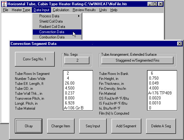
The radiant section for most designs may have up to six different tube segments allowing for different materials, tube sizes, etc. The convection section may have up to ten segments and as many as six different processes.
The primary heater process may be specified for both the radiant and convection section or only in the radiant section.
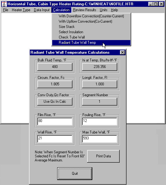
The program allows the user to calculate the radiant tube wall temperatures for different points in different segments, using various factors as described by the user. Tube wall required thickness for all heater sections may be calculated using user specified fluid design conditions and calculated maximum tube metal temperatures with user defined adders or margins.
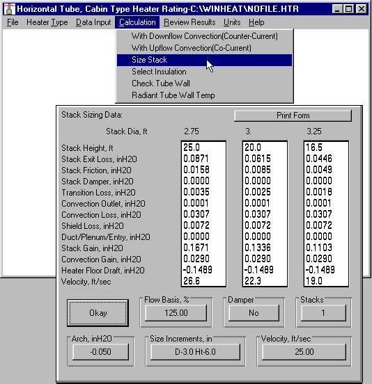
The program allows the user to size the heater stack(s), using program calculated losses and gains in draft, and user specified velocity, bridge wall pressure, and size increments.
Screenshots and Usage
Step 1, Select Heater arrangement Type to be rated Step 2, Select Units for input data(may be changed anytime)
Step 3, Select Process Input, then input process data Step 4, Select Shield Input, then input shield data
Step 5, Select Radiant Input, then input radiant data Step 6, Select Convection Input, then input convection data
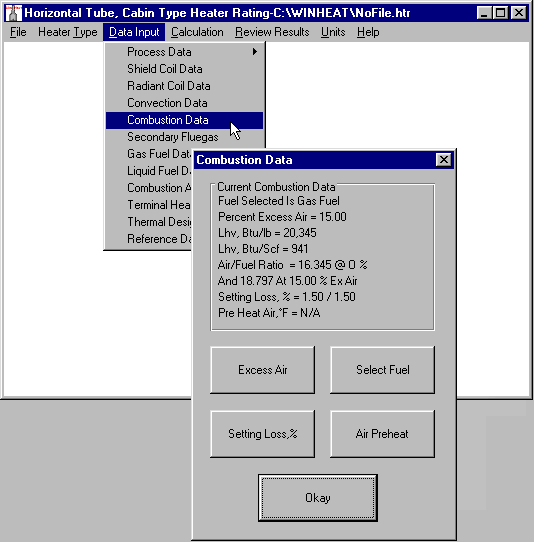
Step 7, Select Desired Fuel Input, then input fuel data Step 8, Select Combustion Input, then set combustion conditions
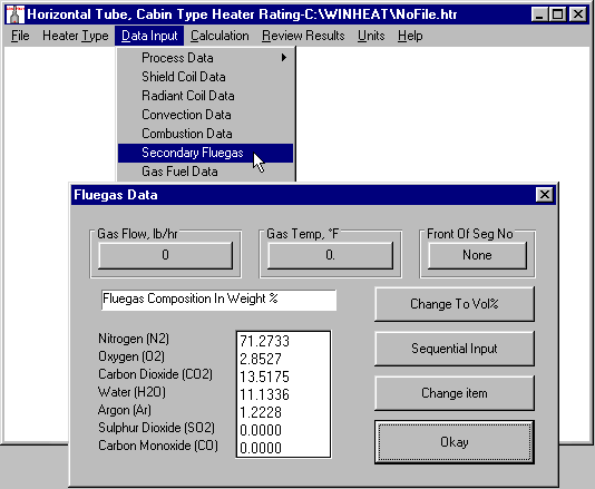
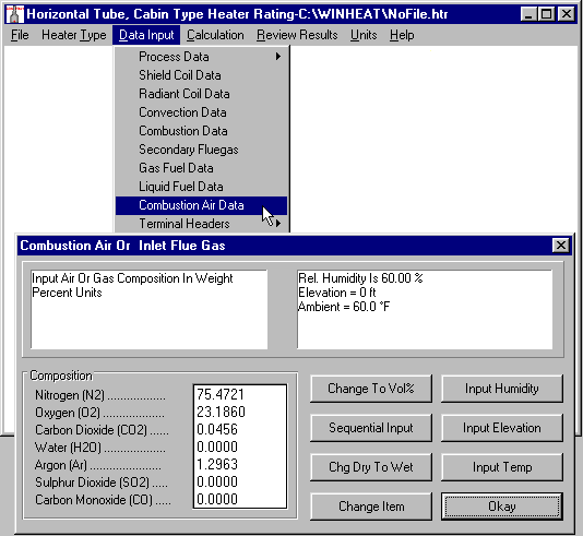
Step 9, If there is a secondary gas stream, Select Secondary Step 10, Select Combustion Air Input, then input conditions
Gas Input then input conditions
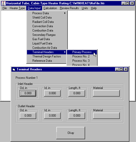
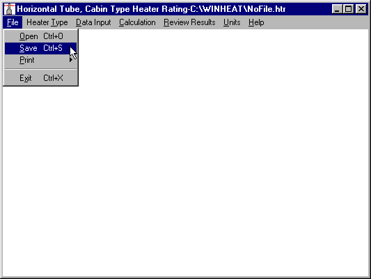
Step 11, If there are inlet or outlet terminal headers, Select Terminal Step 12, SAVE YOUR WORK, Select Save from file menu
Header Input and input
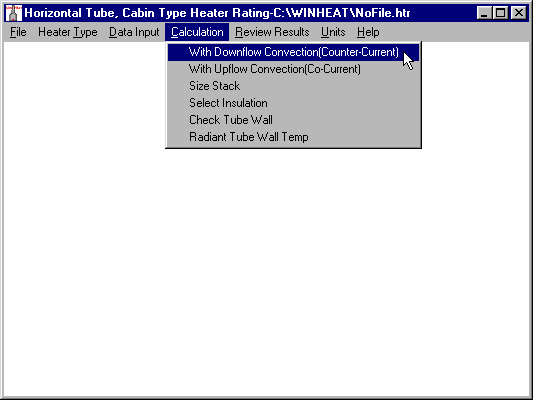
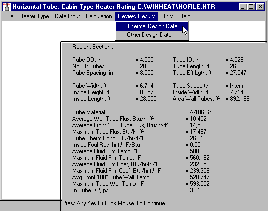
Step 13, Select Calculation Type and run calculations Step 14, Select Review And Type and review on screen
Additional notes on Fired Heater Thermal Design
-
If results of thermal calculations are acceptable, then User should continue, if not, changes should be made, resave file, and rerun
calculations. -
Two available input screens were not reviewed above, they are:
-
-
Reference Data: This form is used to input User project information for identity of data.
-
Thermal Design Factors: This form is used to set or tweak constants used or calculated in the thermal correlations. They should only be manipulated by a heater designer to account for deficiencies such as non-homogeneous radiant gas temperatures, or damaged or fouled fins in the convection section, etc.
-
-
Please continue to review remaining calculations available.
-
View or Print full sample Heater Thermal Printout.
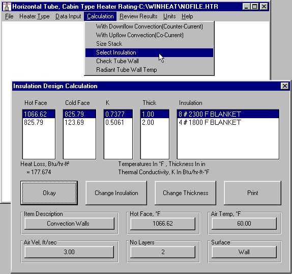
Step 15, Select Size Stack from Calculations, then input Step 16, Select Insulation, then step through each heater -
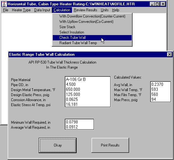
criteria and size stack section setting insulation
Step 17, Select Check Tube Wall from Calculations, then Step 18, Select Radiant Tube Wall Temperature from Calculations, select segment to calculate per API RP530 then set criteria and check as required